This is my final post for this project!!!
Please check out parts 1 and 2 of this project in case you missed them.:
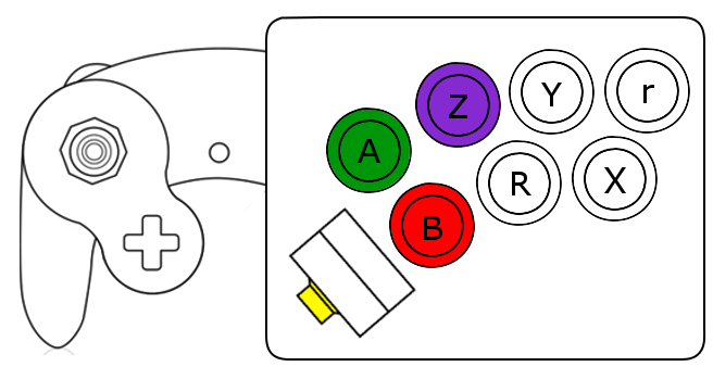 |
| Figure 1: Final concept for modified controller |
Also I don't have access to good tools, so if you're doing a similar project I can't advise you doing this part how I did.
CUTTING UP THE CONTROLLER:
Before starting on the actual box, I prepped the plastic controller so I could better plan out the box's construction. There are two parts of the original controller I want to retain for the new controller: the left hand side, and the c-stick assembly. Figure 2 shows my initial cut to separate the two sides.
 |
| Figure 2: No going back now. |
I then want a flat, perpendicular cut along the left hand side so that it will interface squarely with the box.
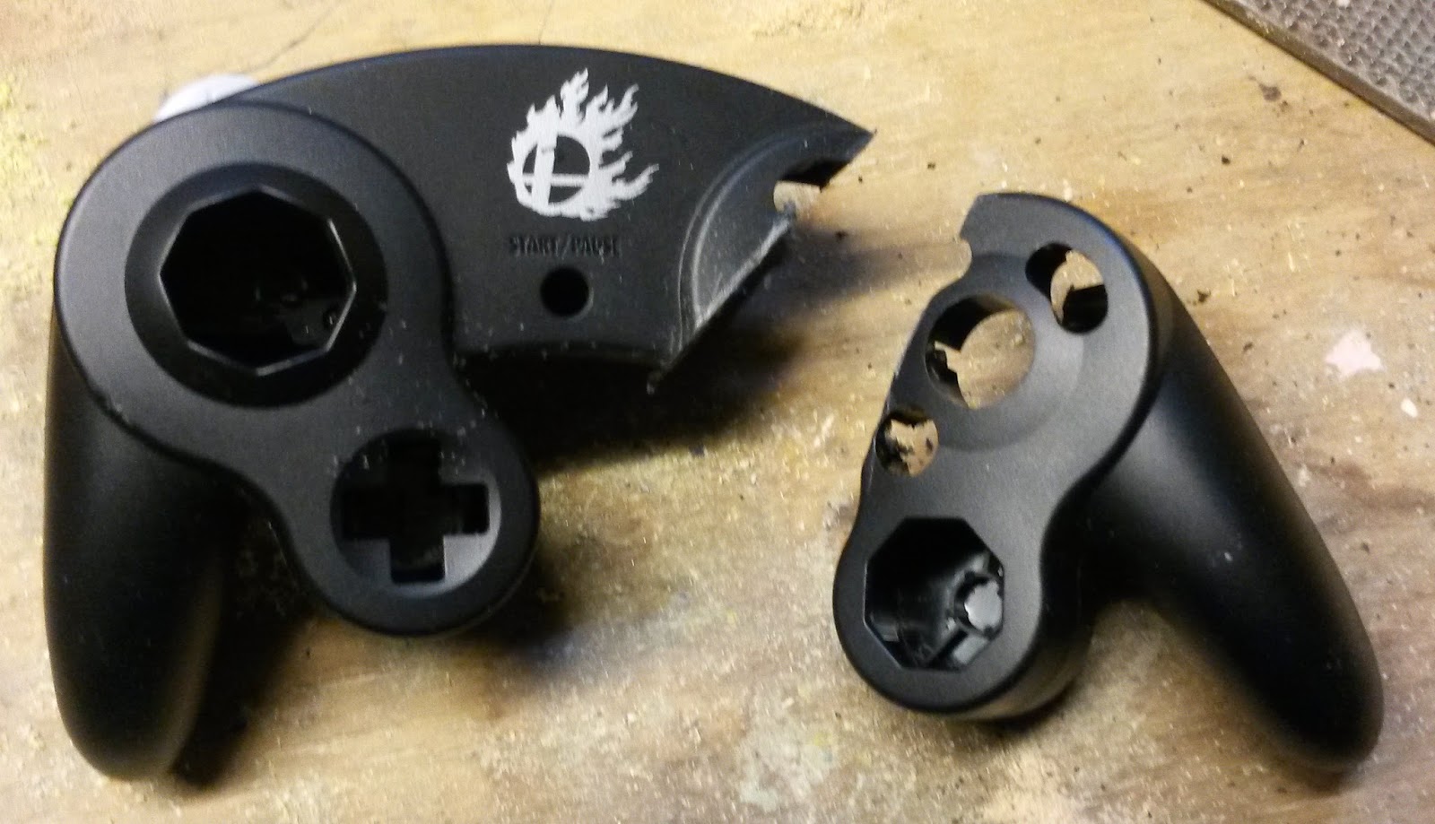
On the c-stick I want just the c-stick housing, so a flat cut was made parallel to the left-right direction of the c-stick. When we rotate the c-stick around 180 degrees from it's original orientation and lay this part flat on the top of our fight stick, up-c will be up and down-c will be down. Figure 3 shows all the cuts I made on the controller. Figure 4 is the left hand piece, and figure 5 is the c-stick piece. Notice how I left the right handle on the c-stick enclosure, This is because it will not get in the way of our final design, and will allow the c-stick enclosure to make a flat seal all the way around when placed on the top of the box.
 |
| Figure 3: Cuts made to controller. |
 |
| Figure 4: Left hand plastic enclosure. |
 |
| Figure 5: C-stick plastic enclosure. |
 |
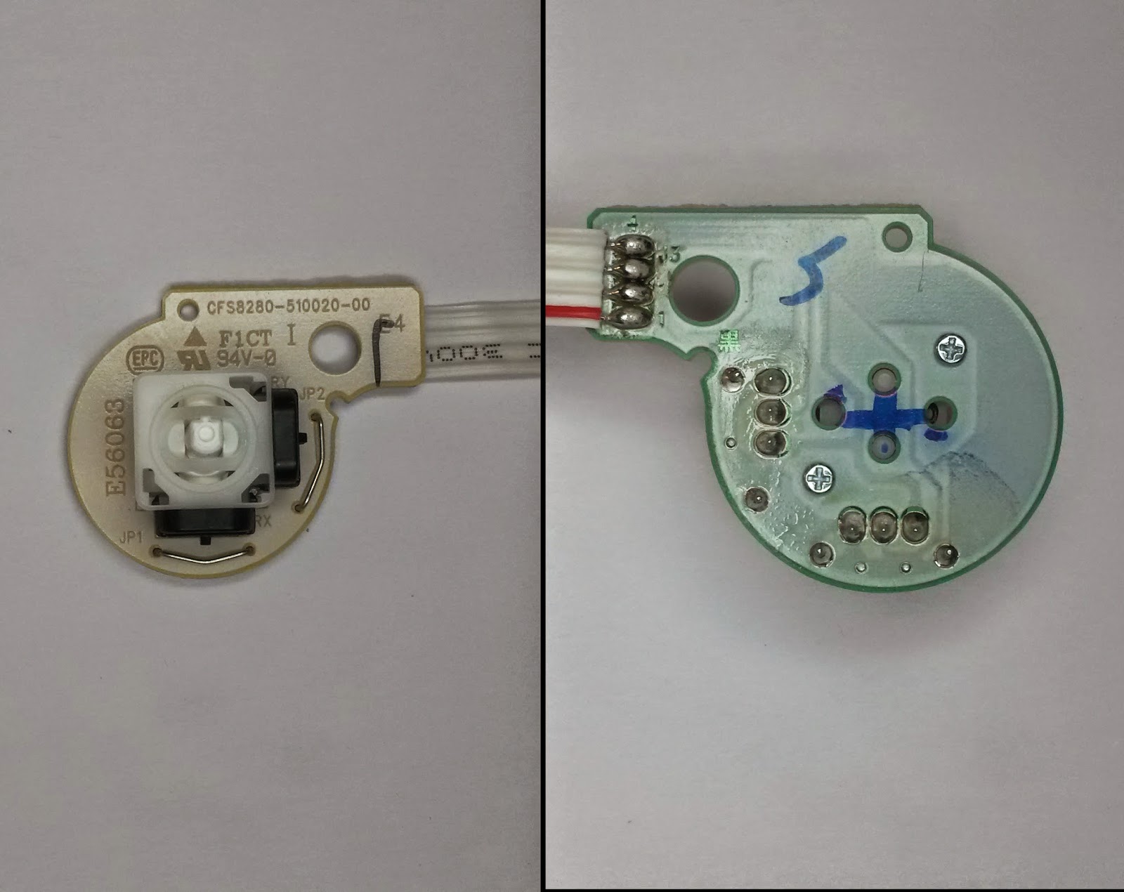
| Figure 6: C-stick assembly highlighting how c-stick is aligned. |
MAKING THE BOX:
This part of the project was by far the hardest for me personally. I have VERY little woodworking experience under my belt, but when building a box I figured getting 4 walls was the place to start. Using a miter box and handsaw I cut 4 planks of oak measuring (2 3/8)"x(3/4)"x(8)". I then glued them flush for the 4 walls as can be seen in figure 7. The walls were then sanded to smooth off the rough cut edges.
 |
| Figure 8: The first step to a box, gluing 4 sides. |
Figure 9 shows me gluing the posts. The top was set under the posts to ensure the top would be flush to the walls once attached.
 |
| Figure 9: Gluing support posts |
 |
| Figure 10: Gluing top onto box. |
 |
| Figure 11: Box with routed edges. |
At this point I drew an outline of where the left hand of the controller was going to connect to the box and used this to route out a hole large enough to pass the circuit board through easily. Figure 12 shows the hole and the controller outline. It's not pretty, but you won't be able to see this once we're done.
 |
| Figure 12: Hole cut for controller pcb to pass into box. |
 |
| Figure 13: Button template printed from hitbox template. |
 |
| Figure 14: Box with button holes drilled. |
 |
| Figure 15: Final coat of stain drying. |
ATTACHING THE CONTROLLER PARTS:
The first thing I did was outline where the c-stick assembly would lay on the box and drilled a hole large enough to pass my wires through (I had to resolder my c-stick wires to the controller afterwards).
I did a little research into what the best adhesive is for gluing plastics (just about everything adheres to wood, so I wasn't too concerned about that). JB Weld plasticweld was highly recommended so I thought I'd try it out. It is a 2 part epoxy that comes in a single tube as a putty. You just kneed the stuff together and you have 20 minutes to work with it. I lined the edge of the c-stick assembly with the stuff and then stuck it firmly against the top of the box. Before it was cured, I used a razor blade to cut away any extra plasticweld.
About 30 minutes later the c-stick is firmly attached to the box (Figure 16)! I'm really happy with the plasticweld!
 |
| Figure 16: Box with c-stick attached. |
 |
| Figure 17: The Final Controller! |
OVERALL IMPRESSIONS AND THINGS I WOULD DO DIFFERENTLY:
The only thing I would really change with this is that I would have moved the start button and controller cord over to the box. I also would have routed out the hole on the wall the left-hand connects to before assembling the box. There is a small part of the hole that is visible because I had difficulty cutting it. Over all I'm very happy with the outcome, and I learned a lot making this thing.
TRIPLE MUSIC BONUS:
One of my best friends and amazing drummer, Jay Carlson, has been spitting out a lot of amazing music lately with his bands Megatherium Club and Fringe Pipes.
The first of these is the Megatherium Club single Preach.
Fringe Pipes' self titled EP was recently released.
And finally both bands participated in St. Olaf's DNNR PRTY which means the release of 2 more singles (Walk Yourself Back Home - Megatherium Club and Prison Cells - Fringe Pipes)
THANKS FOR FOLLOWING THIS PROJECT! Leave me a comment if you have any questions.


.jpg)